The following information was compiled to form the basis of a talk I gave to the Science Group of Warrington University of the Third Age (U3A) in April 2026.
I chose to start with the Rocket because it set the benchmark for all future steam locomotives. I ended with The Duke as it was the final design of steam locomotive built by British Railways for main line operation. The final locomotive was of course Evening Star in 1960.
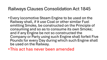
Penydarren
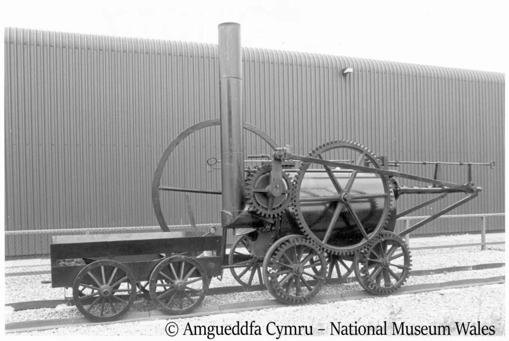
Penydarren was built by Richard Trevithick and made the first locomotive hauled railway journey in the world in 1804. It operated on the nine miles of railway between the iron works at Penydarren and the Merthyr-Cardiff Canal, in Merthyr Tydfil in Wales.
On the first run the engine hauled ten tons of iron in five wagons and seventy men riding on them. The engine achieved a speed of nearly 5 mph.
On the return journey a bolt sheared, causing the boiler to leak. The fire then had to be dropped and the engine did not get back to Penydarren until the following day.
The engine was, in fact, too heavy for the rails. Later, it would serve as a stationary engine driving a forge hammer at the Penydarren works.
It was to be several years before steam locomotion became commercially viable and hence the claim that Richard Trevithick and not George Stephenson was the real father of the railways.
Locomotion No1 – Stockton & Darlington Railway
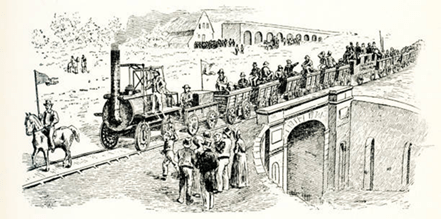
The Stockton & Darlington Railway opened in September 1825. It was the first public railway in the world to convey goods and passengers using steam traction. The first train consisted of six trucks filled with coal, a further six loaded wagons, a passenger coach and twenty-one trucks crowded with people. Stephenson was driving Locomotion and he managed to get the speed up to 8mph.
It was the first locomotive to use coupling rods to link the driving wheels. Earlier engines used a chain or gears.
It used high pressure of 50psi to feed the vertical cylinders.
Locomotion was not George Stephensons first steam locomotive – that was built in 1814. This earlier engine demonstrate that steam locomotives could replace horses. It also demonstrated that metal wheels on metal rails would provide sufficient grip.
Rocket
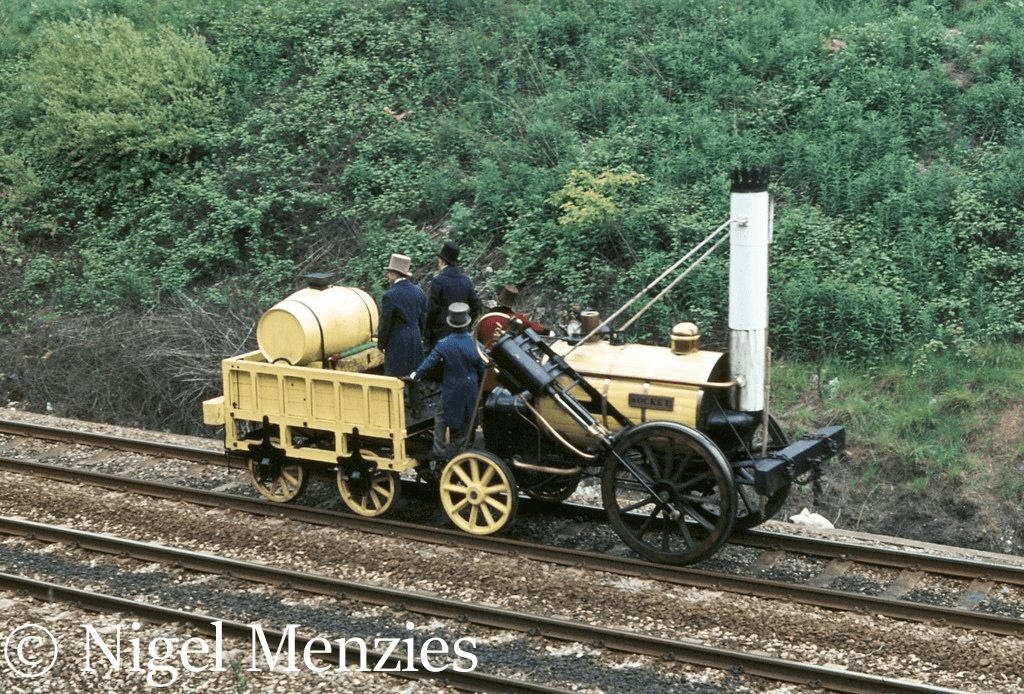
Rocket was built at Newcastle, dismantled and transported to Port Carlisle by cart, then taken to Liverpool by sea before being reassembled
It must be remembered that the Rocket was built to win the competition – Anyone involved in target setting knows the importance of getting them right.
One of the conditions of the trial was that the locomotive had to haul a weight three times greater than its own weight. The locomotive was deliberately built to weigh as little as possible for the trial but this may not have been ideal for working on the railway subsequently. The wheels were made of wood with metal tyres to save weight
Rocket was the only locomotive to complete the trials. It averaged 12 miles per hour (achieving a top speed of 30 miles per hour hauling 13 tons, and was declared the winner of the £500 prize. The Stephensons were accordingly given the contract to produce locomotives for the Liverpool & Manchester Railway.)
the line opened in September 1830.
It was the first railway to have double track for its entire length –
Locomotives of Rocket’s era were fired by coke rather than coal. More on this later.. It was not until 30 years later and the development of the long firebox that locomotives would be able to burn coal effectively.
Within a few years of being built, the Rocket had been much modified. The cylinders were altered to a near-horizontal position, compared to the angled arrangement as new; the firebox capacity was enlarged and the shape simplified; and the locomotive was given a drum smokebox.
It worked on the Liverpool & Manchester Railway until 1836, when it was sold t work at the Naworth collieries at Brampton in Cumberland. This railway was a ten-mile-long track branch railway line on the borders of Cumberland and Northumberland The line connected via spurs to eight collieries.
Rocket was withdrawn around 1840 and it was then stored in a shed until 1851 when it was moved to Stephenson’s works in Newcastle It remained at the works until it became part of the collection at the Patent Museum in 1862.
The Patent Museum subsequently became the Science Museum in London.
In September 2019 Rocket was put on public display at the National Railway Museum at York which is now its permanent home. It is interesting to see it next to a replica which shows it as originally built.
Rocket – Diagram
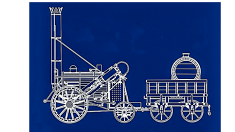
Rocket was the world’s first steam locomotive to combine a multi-tube boiler with draught induced by exhaust steam. This is the principle upon which later steam locomotives operated.
Rocket also used a blastpipe, feeding the exhaust steam from the cylinders into the base of the chimney so as to induce a partial vacuum and pull air through the fire.
Credit for the invention of the blastpipe and the multiple fire-tubes is disputed.
The blastpipe worked well on the multi-tube boiler of Rocket but on earlier designs with a single flue through the boiler it had created so much suction that it tended to rip the top off the fire and throw burning cinders out of the chimney
The steam was directed to the two ends of the cylinders by valves driven by, and linked from, eccentric drivers rotating about the driving axles. The locomotive was reversed by an axial movement of the eccentrics between forward and reverse ‘dogs’ clamped to the axle.
Eat own smoke
Locomotives of Rocket’s era were fired by coke rather than coal. Local landowners imposed regulations on most new railways that locomotives would ‘consume their own smoke
Planet
When the original Planet was built in 1830 it was the ninth locomotive to be built for the Liverpool & Manchester Railway. It was built by Robert Stephenson and was a major advance on Rocket.
It had inside cylinders and a steam dome to prevent water from entering the locomotive’s cylinders,
It was the first locomotive in Britain to have buffers and coupling mechanism.
In November 1830 the locomotive covered the 30 miles between Liverpool and Manchester in one hour.
Original had boiler pressure of 50psi but the replica built in 1992 had a boiler pressure of 100psi due to use of more modern materials.
As the locomotive works of Robert Stephenson were at Newcastle it was considered preferable to build and maintain the locomotives for the line closer. In 1832 Robert Stephenson became a partner in the Vulcan Foundry at Newton le Willows and remained so for a few years.
The earliest authenticated locomotives to be built at Vulcan Foundry were delivered to the Liverpool & Manchester Railway in 1834. Later built locomotives for abroad including Japan and China.
Domed Boiler
The steam dome is a vessel fitted to the top of the boiler of a steam engine. It contains the opening to the main steam pipe and its purpose is to allow this opening to be kept well above the water level in the boiler. This arrangement acts as a simple steam separator and minimises the risk that water will be carried over to the cylinders. where it might cause a hydraulic lock.
Safety Valve
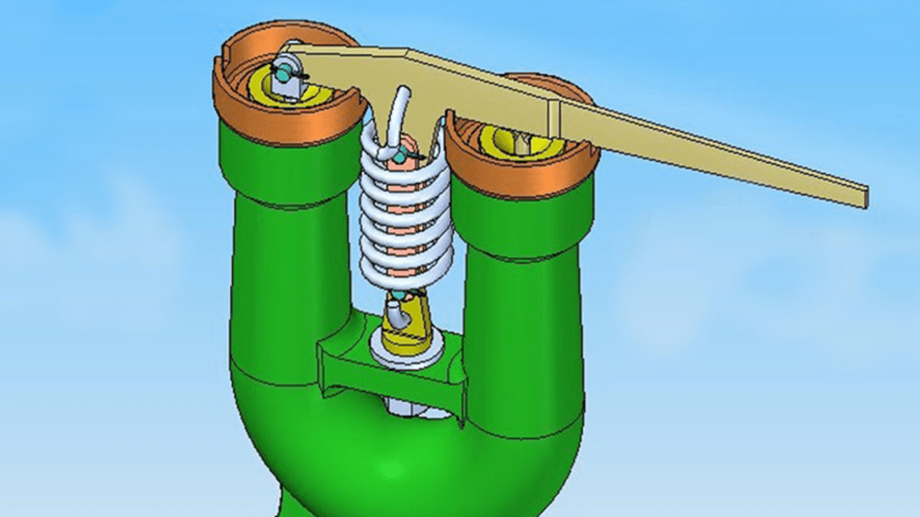
On the Stockton and Darlington Railway, the safety valve tended to go off when the engine hit a bump in the track.It is worth noting that the iron rails on the railway were laid on stone blocks, A valve less sensitive to sudden accelerations used a spring to contain the steam pressure, but these (based on a Salter spring balance) could still be screwed down to increase the pressure beyond design limits. This dangerous practice was sometimes used to marginally increase the performance of a steam
engine.
In 1828, Locomotion was heavily damaged when its boiler exploded killing its driver, The explosion was due to the driver having tied down the safety valve which caused the boiler pressure to rise. This was the third serious accident involving early locomotives in a seven month period.
In 1856, John Ramsbottom invented a tamper-proof spring safety valve that became universal on railways. The Ramsbottom valve consisted of two plug-type valves connected to each other by a spring-laden pivoting arm, with one valve element on either side of the pivot. Any adjustment made to one of valves in an attempt to increase its operating pressure would cause the other valve to be lifted off its seat, regardless of how the adjustment was attempted. The pivot point on the arm was not symmetrically
located between the valves, so any tightening of the spring would cause one of the valves to lift.
The Ramsbottom safety valve became a standard component on many British railways, contributing significantly to the safety and reliability of steam locomotives.
Valve Gear & Cylinders
Valve gear performed three major functions
• The direction the locomotive moved in
• The timing of the steam entering the cylinder to move the piston forcing the driving wheels to turn •
• The timing of the exhaust of steam to the blast pipe and chimney
The valve gear also enable the driver to adjust the point at which the steam is admitted to the cylinder. The greatest power is achieved by keeping the inlet valve open throughout the power stroke. This results in having th e full boiler pressure against the piston throughout the stroke. This is used when starting a train from standing or when working very hard. Peak efficiency is achieved by only having the inlet valve open for a short time and then letting the steam expand in the cylinder which may be possible when the locomotive is running at speed.
The point at which steam stops being admitted to the cylinder is known as the cutoff, and the optimal position for this varies depending on the work being done and the trade off desired between power and efficiency.
Water Troughs
In 1860 the London and North-Western Company decided to accelerate the Irish mail [express train]. John Ramsbottom, then their chief mechanical engineer, was asked to make the run between Chester and Holyhead, nearly 85 miles , in 2 hours 5 minutes. It was clear that if the usual stop on the way to take in water could be avoided, time would be gained.
There were no tenders of sufficient capacity to hold the quantity of water required to enable an engine to run through without stopping. On an ordinary day, from 1,800 to 1,900 gallons ] were consumed, but in the rough and stormy weather frequently experienced along the exposed coast of North Wales it was not unusual for the consumption to rise to 2,400 gallons; whilst the largest tenders only held 2,000 gallons
At a velocity of 15 mph the water is lifted 7.5 ft. The ideal speed to pick up water was 40 – 50 mph.
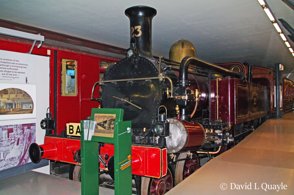
Metropolitan Railway
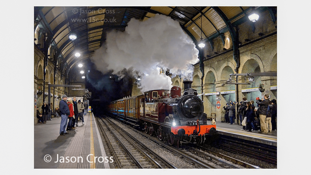
The nearly 4 mile underground Metropolitan railway opened in 1863 from Paddington to King’s Cross and Farrington. It ran beneath Smithfield Market and was used to supply that market.
The locomotives used coke rather than coal. From 1869 Welsh smokeless fuel was used.
It was believed that the railway would be operated by smokeless locomotives and so the line was built with little ventilation.
To solve the ventilation problem this caused the Metropolitan Railway wanted to make more openings in the tunnels. The local authorities argued that these would frighten horses and reduce property
The line was electrified in 1905-6.
A hot brick locomotive had been tried in 1861 but this was an embarrassing failure and in danger of exploding. He bricks were used to retain heat and prevent the smoke escaping.
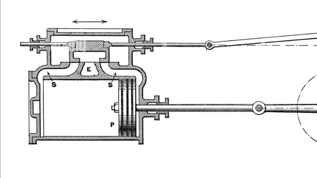
Metropolitan Railway – Condenser
Condensers were Originally developed for the Metropolitan Railway to allow their locomotives to work the tunnels of the London Underground. This system was devised by Daniel Gooch and developed by Beyer, Peacock & Company.
Steam is diverted from the exhaust steam pipes into the water tanks via condensing pipes within the same tanks. The water in the tanks could quickly heat up near boiling point, reducing the condensing effect on the exhaust steam. It was not unknown for the tanks to be emptied and refilled with cold water on a regular basis. Ordinary injectors did will not work with hot water (until hot-water injectors were developed) so condensing locomotives were usually fitted with axle-driven boiler feedwater pumps. When not working in tunnels, the steam was directed to the blast pipe and up the chimney in the usual way.
Belphaire Boiler
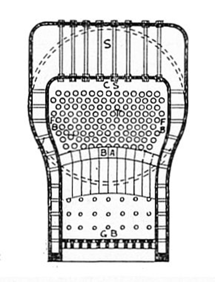
The Belpaire boiler was invented by Alfred Belphaire of Belgium in 1864. It now often referred to as the Belphaire Firebox.
The main advantage of the design is that there is a greater surface area in the boiler near the firebox where the heat is greatest.
Most British steam locomotives built after 1920 used Belphaire boilers.
Stopping
As locomotives became capable of going faster and pulling heavier loads one major problem was still to be overcome – how to stop.
Anyone who has taught anyone to learn to drive a car will recognise this concern.
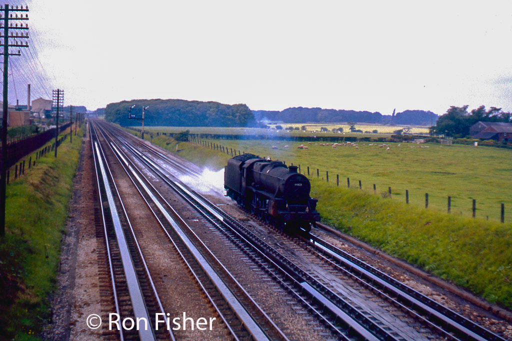
This locomotive for instance could handle light loads at speeds up to 85mph – Heavy loads of 275 tons reduced the possible speed to 50mph.
In the earliest days of railways, trains were slowed or stopped by the application of manually applied brakes on the locomotive and in vehicles through the train.
Brakes were applied following a signal from the driver using the locomotive whistle.
This was clearly unsatisfactory, given the slow and unreliable response times. Each vehicle brake had to be applied separately by a member of the train crew.
Vacuum Brakes
A major advance was the adoption of a vacuum braking system around 1873
The brakes were activated by the vacuum moving a piston in each coach. The piston moved as there was air on one side and a vacuum on the other.
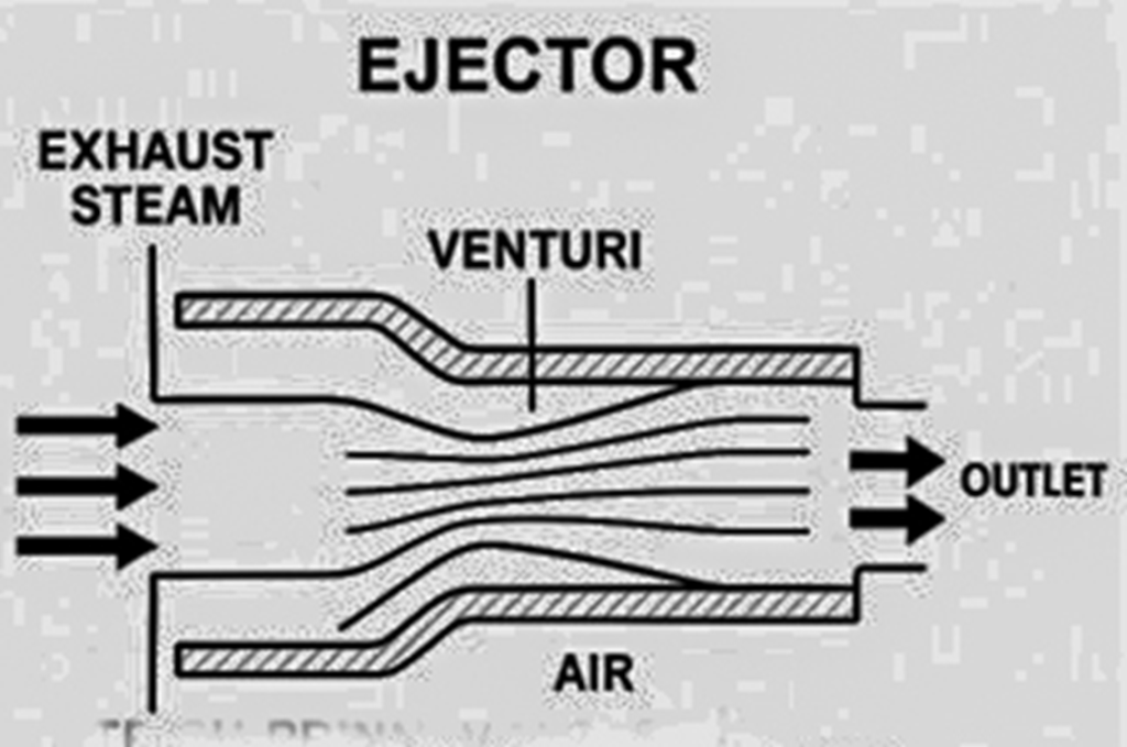
Vacuum was preferred because steam locomotives can be fitted with ejectors; venturi devices that create vacuum without moving parts.
In response to the defects the automatic vacuum brake was developed.
This system required the chose running throughout the train to be filled with a vacuum to keep the brakes off rather than on.
The automatic vacuum brake was slightly more expensive to manufacture, install and operate as the ejector ran continuously (at a cost in steam and thus fuel and water)
Armagh, N Ireland – 1889
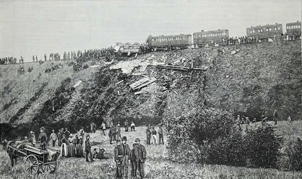
In 1889 in Armagh a crowded Sunday School excursion of 15 coaches with 940 people aboard failed to climb a steep incline. The locomotive stalled about 200 yards before the summit. The crew decided to split the train..
As the vacuum braking system was not automatic it did not work on the rear portion once the train had been split. The only brakes in the rear section were the hand operated ones in the rear brake van.
When the front portion of the train set off the rear portion then set off down the incline and collided with a following train.
80 people were killed and 260 injured.
within two months of the Armagh disaster Parliament enacted the Regulation of Railways Act 1889, which authorised the Board of Trade to require the use of continuous automatic brakes on passenger railways, along with the block system of signalling and the interlocking of all points and signals.
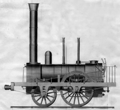
Superheaters
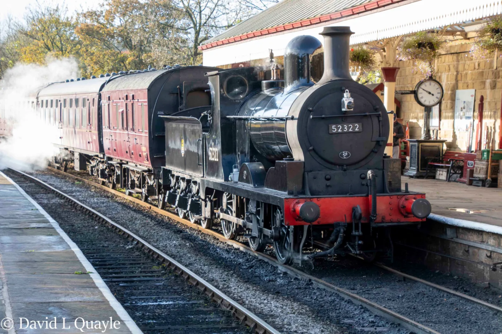
In 1899 the Lancashire & Yorkshire Railway became the first railway in Britain to fit a locomotive with a superheater in 1899.
It was one similar to this which was built in 1895 and has a saturated boiler as it does not have a superheater.
The first locomotive with a superheater entered service in Prussia in 1898.
Superheaters – Diagram
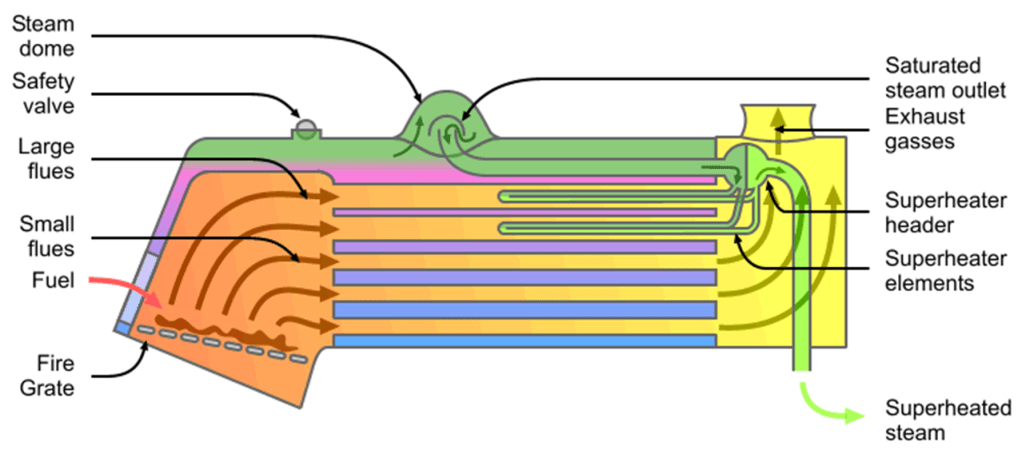
. This followed a period of investigations by Dr Schmidt which extended over a forty year period. He is considered to be the pioneer of practical superheating. He was the first to risk increasing the temperature of the steam up to 350 °C.
TA superheater is a device fitted inside the boiler that raises the temperature of the steam above its boiling point, producing superheated (dry) steam instead of ordinary saturated (wet) steam.
The steam produced in the boiler is called saturated steam as it contains tiny water droplets.
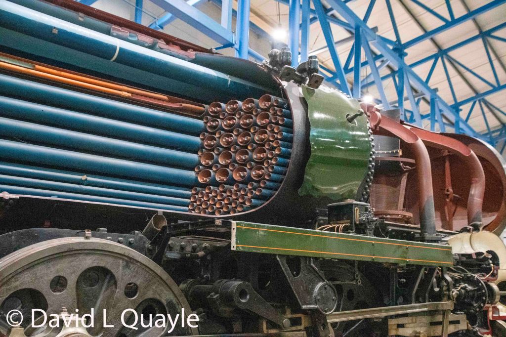
With a superheater the steam is routed through superheater elements which are long steel tubes with a small diameter which are inside the large flue tubes of the boiler. The result is superheated steam, which is hotter, drier, and more efficient.he superheaters used on British steam locomotives were variations of his design.
Motor Coach
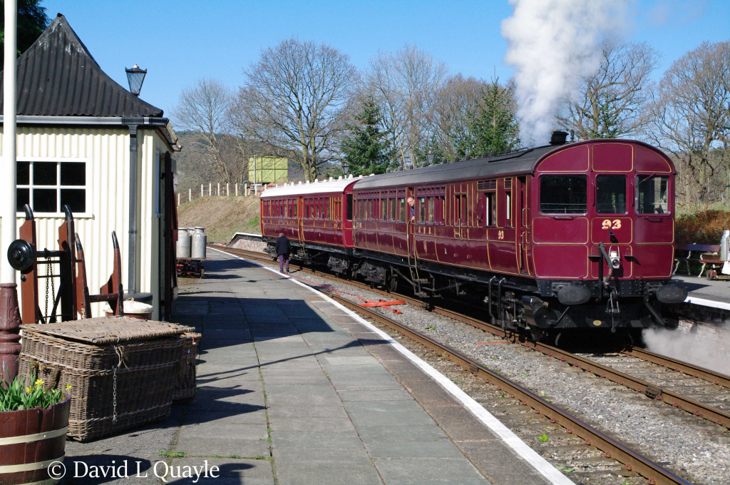
In the first years of the twentieth century, railway managements turned their attention to the need to provide better local passenger services and to reduce costs.
Motor coaches were designed to be used on rural routes and had the benefit that they could be driven from both ends.
The steam locomotive component was quite small and had limited power. They had vertical boilers rather than the normal horizontal boiler.
opening the firehole door immediately sent cold air straight up the vertical flu tubes thus lowering the temperature and subsequently loosing pressure.
The firemen therefore adopted the approach of only feeding coal into the firebox when the steam motor was stationary.
Push & Pull
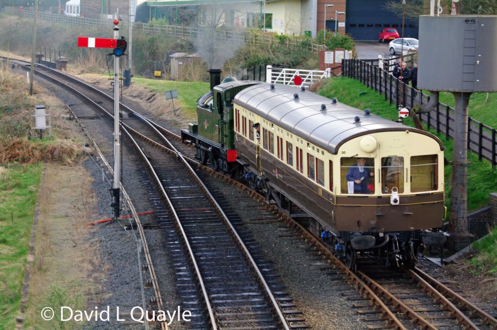
Autotrains or Push & pull was a development of the motor coach approach. The difference being the locomotive was attached to the coach or coaches rather than part of a coach. This approach met the need to be able to drive the train from both ends – either from the locomotive or lead coach.
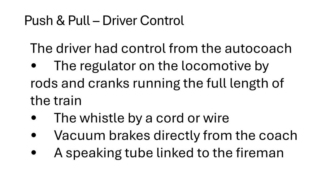
Push & Pull – Driver Control
Midland Compound – Johnson 1902
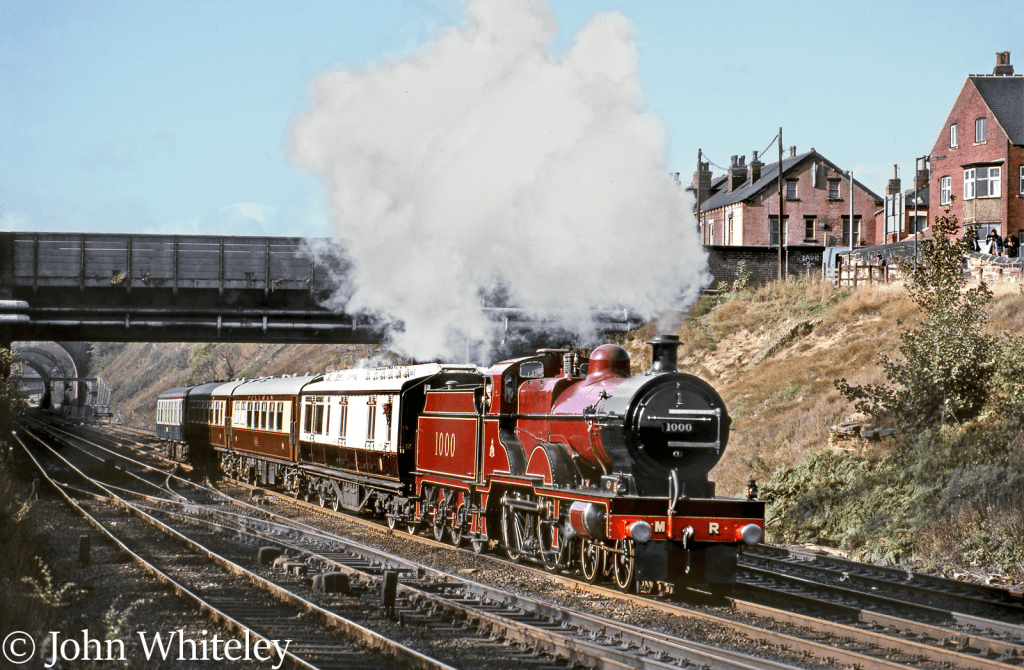
The use of compound engines goes back to the middle of the 19th century, but these were static engines. They were called compounds because they used the steam twice so saving coal.
Several railways had experimented with compound engines in the latter part of the 19th century. But with somewhat indifferent results.
The Midland compound engines are considered by some to have been the only really successful compound locomotives ever to work in this country.
designed by Johnson and built at Derby in 1902
They had one inside high pressure cylinder and two outside low pressure cylinders.
The steam at 200psi was fed from the regulator to the high pressure cylinder as for a standard locomotive. The exhaust from the high pressure cylinder was fed to the two low pressure cylinders. Upon leaving the low pressure cylinder the exhaust was sent to the blast pipe and out of the chimney.
The Chief Mechanical Engineer wanted to look further at using the compound approach the Chairman instructed such work to stop as other improvements were being looked at.
Fireless Locomotives
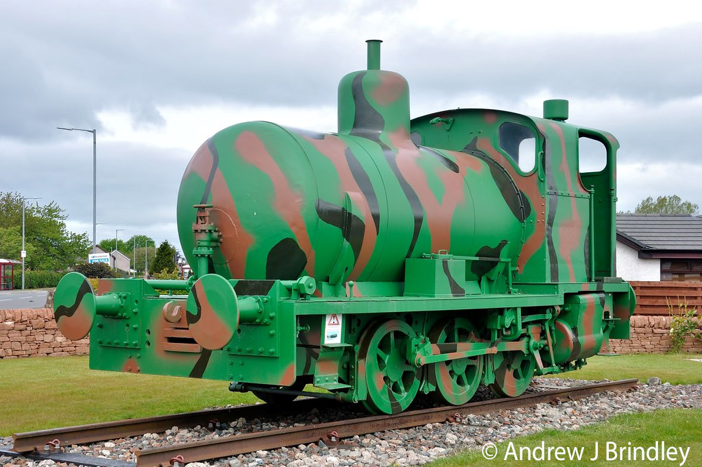
This is a fireless steam locomotive at the Devil’s Porridge Museum at Gretna.
First fireless locomotive 1912.
They were used where the use of a conventional steam locomotive represented too high a risk of fire or explosion from any sparks. The engines delivered to the Ministry of Munitions had rail washing gear fitted to the wheels to reduce the risk of sparks by easing the travel over sharp radius curves.
A fireless steam locomotive has a reservoir, known as a steam accumulator, instead of a boiler. This reservoir is charged with superheated steam under pressure from a stationary boiler.
As the steam is used and pressure drops, the superheated water boils, replacing the used steam until in needs recharging.
They were very economical as shunters when there is a good supply of steam available.
Castle Class
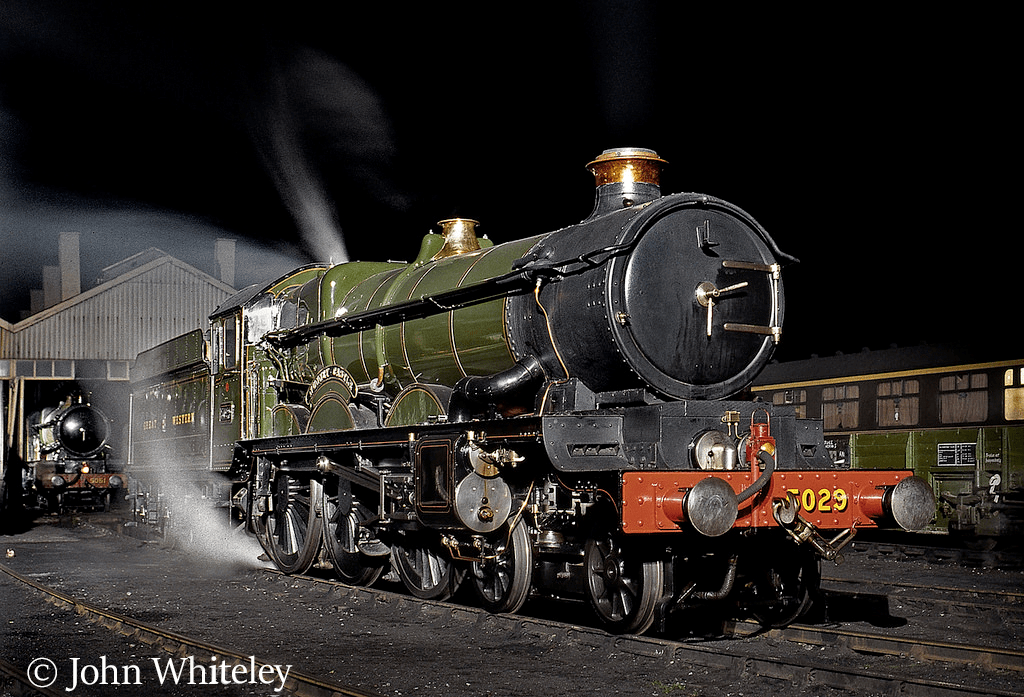
171 Castle class locomotives were built at Swindon over the period 1923 to 1950. I don’t know of any others produced over such a long time. They had a major influence on the design of locomotives in all of the major railway companies.
Designed to haul heavy express trains but stay within the axle load limit at that time of 20 tons.
The shape of the Belpaire boiler can be seen.
Also the tapered boiler
Engineered for efficiency rather than brute force
The Belphaire boiler design was improved by tapering the boiler.
the largest area being at the front of the firebox where the heat was greatest.
The blastpipe and chimney optimised the airflow
The locomotive had four cylinders
Burned 40-45lb of coal per mile hauling express trains
Consumed 25-30 gallons of water a mile
Castle Class – Optical Measurement
•Locomotive alignment between the frames, cylinders and axles box guides was made by using wires, trammels and a centre prop
•
•The original methods were effective but limited by human error and mechanical constraints, often resulting in tolerances of 0.25–0.5 mm.
•Optical methods introduced in 1934 reduced tolerances to 0.025–0.05 mm
King Class
The King Class locomotives were introduced in 1927.
They were an enlarged version of the Castle Class.
They were the first British locomotives to have boiler pressures of 250psi. The Castles were 225psi.
The Castles had been limited to boilers of a 5′ 6″ because of concerns that a larger boiler would be too heavy for some bridges. Following the strengthening of bridges
And a better understanding of the hammer blow from the cylinders the restrictions were relaxed.
The King had the highest permissible axleload of 22½ tons, and the largest firegrate. The tractive effort was regarded as important for publicity purposes and for this reason the cylinders were 16¼in rather than 16in in order to achieve a tractive effort in excess of 40,000lbf.
As a result of their weight the locomotives were restricted to the heaviest main lines only so were largely used between Paddington -Bristol and Paddington – Birmingham. They were also restricted as Wide and tall which placed restrictions on where they could go.
Mallard – World Record Holder
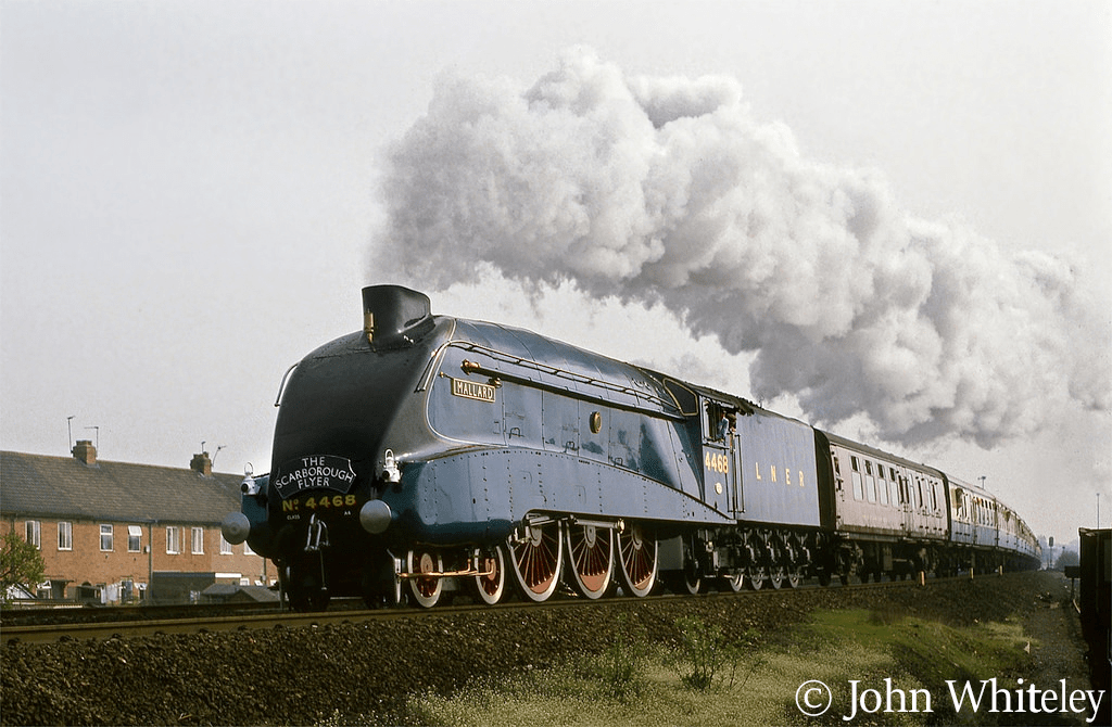
In the early 1930s the LNER was considering providing high speed services between London and Newcastle. At first the possibility of a diesel-electric train was considered, based on the German Flying Hamburger train.
The first of the new A4 class was completed at Doncaster in 1935. It was a development of his A3 class of which Flying Scotsman was a member.
This wedge-shaped streamlining on the A4 was inspired by a Bugatti rail-car which Gresley had observed in France. The design was refined with the help of Prof. Dalby and the wind tunnel facilities at the National Physical Laboratory (NPL) at Teddington. As well as streamlining, it was important that the design lifted smoke up away from the cab. At first, there was a lot of difficulty in achieving this. During the wind tunnel tests, it was noticed that a thumb print had inadvertently been added to the plasticine model, just behind the chimney. re-tested with the thumb print the smoke was lifted well clear of the cab.
Mallard is the holder of the world speed record for steam locomotives at 125.88 mph. The record was achieved in 1938.
Mallard was one of a few of the class built with a more powerful plast-pipe and double chimney which considerably improved the running at high speeds compared to the rest which had single chimneys. It was found that the economy obtained over the single chimney was from six to seven pounds of coal per mile, which more than justified the expense of the conversion.
A rather weird wartime change, was the removal of most of the chime whistles. It was thought that these might be confused with air-raid sirens. These were removed in 1942 and destroyed. New chime whistles were fitted after the war.
Turbo – 1935
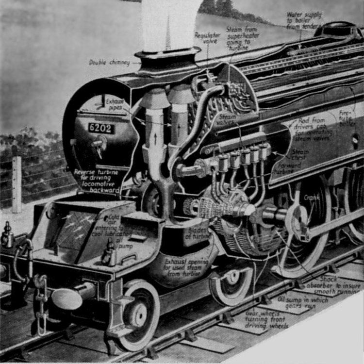
- In 1935 one of the class entered service which had turbines instead of cylinders. The boiler pressure remained at 250psi.
- One had 18 rows of blades and was for forward motion. The turbine on the other side had only four rows of blades and was only powerful enough to move only the engine itself.
- The power was controlled by using the six different sized nozzles which directed the steam admitted into the turbines.
- As the turbines spin at very high speeds the power was transmitted to the driving wheels through gearing and a mechanical drive shaft system to deliver a slower more usable speed to the middle driving axle.
- Many snags were encountered but when it was in service it was a very good engine.
- When a turbine failure occurred in 1949, it was considered uneconomic to repair, due to post-war austerity measures, so the locomotive was taken out of service pending a rebuild. It was rebuilt as a conventional locomotive in 1952 but only lasted in service for two months as it was very badly damaged in a rail crash at Harrow. 112 died in this accident which involved three trains.
- The accident accelerated the introduction of Automatic Warning System – by the time the report had been published British Railways had agreed to a five-year plan to install the system that warned drivers that they had passed an adverse signal.
- lide 31 – Duke of Gloucester
Coronation
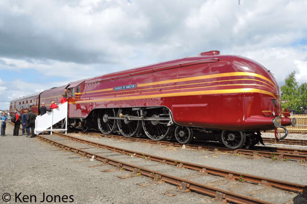
In 1937 following the success of the Princess Royal class, Stanier developed an improved design of pacific for working the newly inaugurated high speed service between London and Glasgow. They are regarded as the largest and most powerful express passenger steam engines to be built for service in Great Britain. The estimated at 3300 horsepower and making them far more powerful than the diesel engines that replaced them.
The power of a steam locomotive is defined in terms of tractive effort and for a Duchess Coronation it was calculated at 40,000 lbf.
Tractive effort refers to the pulling force that a locomotive can exert on the train it is hauling. It is a critical measure of a locomotive’s performance, especially for steam locomotives, where it often limits the size of the train that can be pulled. Tractive effort is typically highest when the locomotive is stationary, known as starting tractive effort, and decreases as speed increases due to various mechanical factors.
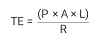
Where:
- TE = Tractive Effort
- ( =Mean effective pressure in the cylinders
- A=Area of the piston
- L=Stroke length
- R=Radius of the driving wheel
These locomotives had a considerably larger heating surface than the Princess class but weighed only one ton more. \they also had improved superheaters.
The saving in weight of the Duchess was achieved by using nickel steel rather than mild steel. By using 2 % nickel steel almost two tons was saved on the weight of the boiler.
In order to meet the challenge of Gresley’s streamlined pacifics on the LNER some of these engines were also streamlined. At high speed streamlining did actually serve a useful purpose by reducing air-resistance ..
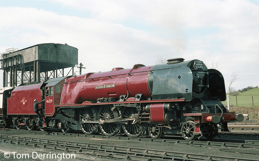
From 1946 onwards the streamlining was removed as it was found that it was of little value at speeds below 90mph and it was a nuisance to the maintenance staff.
An unusual feature of Coronation Class tenders was that they were fitted with a steam-operated coal pusher to bring the coal forward.
quipment greatly helped the locomotives fireman to meet the high demands for power during the non-stop run of 299 miles between London Euston and Carlisle.
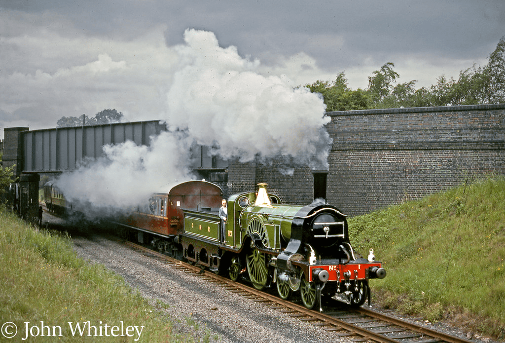
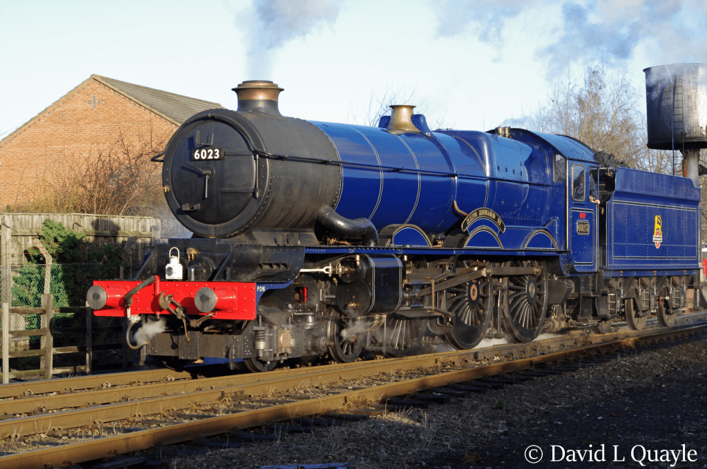
Duke of Gloucester
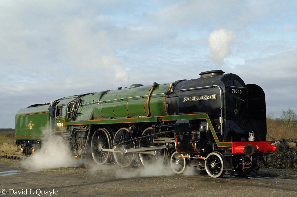
The Duke was the replacement the locomotive for the Princess Class locomotive badly damaged in the Harrow crash.
Aim was to develop an a more powertful version of an express locomotive introduced in 1951 – Britannia.
The Britannia class had two cylinders and to achieve the power required for the major express tasks that the locomotive was required for meant that the cylinders would be larger. This was not possible as it would take the locomotive outside the British loading gauge.
There was a reluctance to use three-cylinders due to the experience with the Gresley pacifics whose conjugated valve gear was difficult to maintain due to the location of the middle cylinder between the frames.
The solution to this issue was to use three-cylinders with a modified Caprotti valve gear.
The Duke of Gloucester entered service in May 1954.
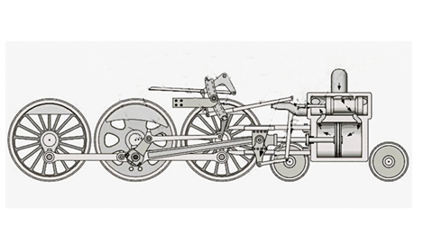
Caprotti Valve Gear
The Caprotti valve gear was invented in 1928. It used the principle of the poppet valve from the motor car.
the novel rotary cam-driven British Caprotti valve gear developed by Heenan & Froude.
In 1950 Tom Daniels, Chief Engineer for Associated Locomotive Equipment invented an assembly which became known as the British Caprotti valve gear Daniels was a former GWR engineer.
This allowed precise control of steam admission to the cylinders while improving exhaust flow and boiler draughting compared to the earlier valve gear.
The benefit of the British Caprotti valve gear is that the poppet vales open more quickly than using pistons and provide a more efficient steam flow.
It also creates a shorter more forceful exhaust pulse entering the blast pipe.
The Duke – 1967 – 1974
The British Caprotti company, recommended the use of the Kylchap blastpipe, to cope with the fierce exhaust blasts. A standard double chimney of the Swindon type had already been fabricated in order to cut costs and it had been The chihimney and blastpipe were much too small leading to poor draughting.
Faults later discovered that the ashpan did not allow the flow of air required of the fire.
As a result of the 1955 Modernisation Plan the Duke remained the sole member of the class and most of the problems were never ironed out before its withdrawal from service in November 1962.
Sold for scrap in 1967. Initially towed to Cashmore’s.By chance it was noticed that the destination label on the Duke read Woodham’s, Barry. \the remains of the Duke were towed to Dai Woodham at Barry.
Over 150 locomotives from the Barry scrapyard have steamed again in preservation.
The Duke Reborn
After withdrawal in November 1962, the Duke was initially selected for the National Collection, Only the cylinder arrangement was of interest. It is understood that the reason the locomotive was not preserved was because of lack of space at the Railway Museum at Clapham.
What was left of the Duke eventually left the Barry April 1974.
After much work the Duke steamed again in 1986.
In October 1995 7It climbed Shap and topped the summit at the highest speed ever attained by a steam locomotive with a heavy load. 51mph.
A former Crewe Fireman (Ray Hatton) stated that in the old days if he was rostered to fire the Duke he would rather go sick than endure the ordeal of trying to raise steam with the engine. Having gained experience as a driver of the locomotive in 1990 he was astonished at the transformation in the
The Duke is now one of the most powerful steam locomotives ever to run on Britain’s railways. It is more powerful than the English Electric Type 4 diesel locomotives which replaced it.
